When you work with an oscilloscope, you often see a button or menu labeled “AC/DC Coupling.” At first, this may seem confusing. What does it really mean? Why does it matter? This choice can change what you see on your screen, how you analyze signals, and even how you solve electrical problems. Understanding the difference between AC coupling and DC coupling is not only important—it’s essential for anyone using an oscilloscope, whether you’re a student, hobbyist, or professional.
Let’s explore this topic step by step, with practical examples, clear comparisons, and real insights you won’t find in basic guides.
What Is Oscilloscope Coupling?
An oscilloscope measures voltage over time. But not every signal is the same. Some signals have a steady part (DC), some change over time (AC), and many have both. Coupling is how your oscilloscope connects to the signal. It decides which parts of the signal pass through to the screen.
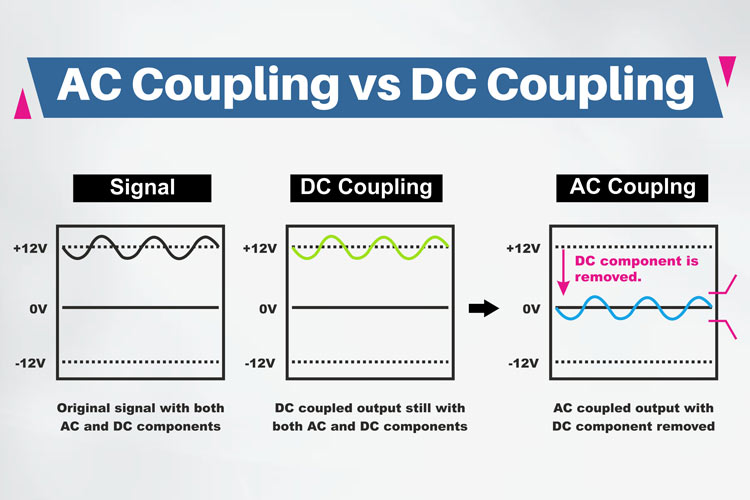
- DC Coupling shows both the steady (DC) and changing (AC) parts.
- AC Coupling blocks the steady part, so only the changing (AC) part appears.
The right choice depends on what you want to see or measure. This setting is a simple switch, but it can transform your results.
Dc Coupling Explained
When you select DC coupling, your oscilloscope connects directly to the input signal. Nothing is blocked. You see the full waveform: any constant voltage and any variation.
Typical Uses For Dc Coupling
- Measuring battery voltage
- Checking power supply rails
- Observing digital signals (logic levels)
- Viewing mixed signals (AC riding on DC)
For example, suppose you want to measure a sensor output. If the sensor produces 2 volts steady (DC) plus a small vibration signal (AC), DC coupling shows both. You can see the baseline and any movement.
How Dc Coupling Works
Inside the oscilloscope, DC coupling is straightforward. The input signal passes straight to the amplifier and display. No filter is added. This means you can measure true voltage levels, including any offset.
Example: Digital Communication
Digital signals often have a steady baseline, like 3. 3 volts, but the actual message is sent by quick changes. DC coupling lets you see both the baseline and the data pulses.
Non-obvious Insight 1
Many beginners forget that DC coupling is necessary when measuring absolute voltages. If you want to know the real value, not just changes, always use DC coupling.
Ac Coupling Explained
When you choose AC coupling, your oscilloscope adds a special filter—a capacitor—between the probe and the input. This filter blocks steady voltages (DC) but lets changing signals (AC) through.
Typical Uses For Ac Coupling
- Viewing small signals on large DC offset
- Checking noise or ripple on power rails
- Measuring audio waveforms
Imagine you want to see a tiny signal (0. 01 volts AC) sitting on a big DC voltage (10 volts). DC coupling would show the whole signal, but the tiny part would be hard to spot. AC coupling removes the baseline, so you focus on the small changes.
How Ac Coupling Works
The capacitor acts like a gate. DC (steady voltage) cannot pass, but AC (changing voltage) goes through. This is especially useful when the DC part is much bigger than the AC part.
Example: Audio Signal
Suppose you connect an oscilloscope to an audio amplifier output. The signal may have a DC offset, but you only care about the sound waves (AC). AC coupling removes the offset, making the waveform easier to analyze.
Non-obvious Insight 2
AC coupling doesn’t just remove DC—it can change the shape of low-frequency signals. If the signal changes slowly, the oscilloscope may distort it. Beginners often miss this, leading to wrong measurements.
Ac Vs Dc Coupling: Key Differences
To make things clearer, here’s a comparison table:
| Feature | DC Coupling | AC Coupling |
|---|---|---|
| Shows DC component? | Yes | No |
| Shows AC component? | Yes | Yes |
| Removes DC offset? | No | Yes |
| Best for low-frequency? | Yes | No (can distort) |
| Typical use case | Power supply, logic | Audio, noise analysis |
| Component used | Direct connection | Capacitor filter |

Credit: electronics.stackexchange.com
Real-world Examples
Example 1: Measuring Ripple On A Power Supply
Imagine you want to check a 5V power rail for ripple. The ripple is small AC (maybe 20 mV) on a large DC (5V). If you use DC coupling, the oscilloscope shows 5V with tiny bumps—hard to see. Switch to AC coupling, and the 5V disappears, so you can zoom in on the ripple.
Example 2: Debugging A Sensor Signal
You connect a sensor that gives a 3V baseline with superimposed AC vibrations. If you use AC coupling, the baseline goes away, and only the vibration is visible. If you want to measure the real voltage (including baseline), use DC coupling.
Example 3: Audio Waveform Analysis
Audio signals are pure AC. But sometimes, the circuit adds a DC offset. AC coupling removes the offset, so you see the waveform clearly. This is why AC coupling is common for audio work.
When To Use Each Coupling Mode
Choosing between AC and DC coupling depends on your goal.
- Use DC coupling when you need to measure the true voltage, including any offset.
- Use AC coupling when you want to see only the changes, ignore the baseline, or focus on small AC signals.
Here’s a quick decision guide:
| Situation | Best Coupling |
|---|---|
| Measuring battery voltage | DC |
| Analyzing audio signal | AC |
| Finding noise on power rail | AC |
| Debugging digital logic | DC |
| Viewing small AC on large DC | AC |
Common Mistakes And How To Avoid Them
Many users make errors with coupling settings. Here are the most frequent mistakes:
- Using AC coupling for slow signals: AC coupling can distort slow-changing signals. Always check the frequency. If the signal is below a few Hz, DC coupling is safer.
- Measuring absolute voltage with AC coupling: AC coupling removes the baseline. If you want the true value, use DC coupling.
- Forgetting to switch back: After using AC coupling, some users forget to return to DC coupling. This can lead to wrong results in later measurements.
- Not understanding the filter effect: AC coupling uses a capacitor. This creates a “high-pass filter,” which blocks low frequencies. If your signal has slow parts, they may disappear or look wrong.
Advanced Details: Frequency Response
Oscilloscopes use a capacitor for AC coupling. This creates a filter with a cutoff frequency. Signals below this frequency are blocked or distorted.
For example, if the cutoff is 1 Hz, signals slower than this may not appear correctly. This matters for low-frequency analysis.
Cutoff Frequency Formula
The cutoff frequency depends on the capacitor size and the oscilloscope’s input resistance. The formula is:
f = 1 / (2πRC)
Where:
- F is the cutoff frequency
- R is input resistance (often 1 MΩ)
- C is capacitor value (often 0.1 µF)
If you know these values, you can calculate the lowest frequency your oscilloscope shows accurately in AC mode.
Practical Tips For Better Measurements
- Always check your coupling setting before starting.
- For mixed signals (AC + DC), start with DC coupling to get the full picture.
- If the signal is too large to display, switch to AC coupling to focus on changes.
- Adjust vertical scale after switching modes—AC coupling removes the baseline.
- If you’re measuring low-frequency signals, stick to DC coupling unless you know the cutoff frequency.
- Mark your probes and cables to remind yourself of the current setting.
Ac/dc Coupling On Different Oscilloscope Types
Modern oscilloscopes (digital or analog) offer both coupling modes, but the implementation may differ.
- Analog scopes: Switch adds a capacitor directly.
- Digital scopes: Software or hardware filter applies the effect.
Some scopes allow you to set the cutoff frequency. Others have fixed values. Always check your oscilloscope’s manual.
Example: Tektronix Oscilloscope
A Tektronix digital oscilloscope lets you choose AC/DC coupling per channel. AC coupling uses a 0.1 µF capacitor, giving a cutoff around 1.6 Hz.
Credit: components101.com
Comparison With Other Instruments
Oscilloscopes are not the only devices with coupling options. Signal analyzers and audio testers also offer AC/DC coupling, but the cutoff frequency may vary.
For deeper technical details, official manuals and application notes can help. For example, Wikipedia’s oscilloscope page explains coupling in context.
Frequently Asked Questions
What Is Ac Coupling On An Oscilloscope?
AC coupling uses a capacitor to block steady (DC) voltage, allowing only changing (AC) signals to reach the screen. It’s useful for viewing small AC signals on a large DC offset.
When Should I Use Dc Coupling?
Use DC coupling when you need to see the real voltage level, including any steady (DC) part. This is important for power supplies, battery measurements, and digital signals.
Can Ac Coupling Distort My Signal?
Yes, especially for low-frequency or slow signals. The capacitor acts as a filter, so signals below the cutoff frequency can appear distorted or disappear.
Why Does My Waveform Shift When I Switch To Ac Coupling?
Switching to AC coupling removes the DC baseline. The waveform centers around zero, so only the changing parts remain. This is normal.
Is Ac/dc Coupling Available On All Oscilloscopes?
Most modern oscilloscopes offer both AC and DC coupling. Some older or basic models may only have DC coupling. Always check the features before buying or using an oscilloscope.
Understanding AC vs DC coupling on an oscilloscope helps you make better measurements, avoid mistakes, and solve electrical problems faster. With these insights, you can use your oscilloscope more confidently and get more accurate results.

Credit: www.youtube.com