Is your vehicle acting up, or is the ignition system not firing properly? If you suspect your ignition control module might be the problem, you’re in the right place.
Knowing how to test your ignition control module with a multimeter can save you time, money, and frustration. In this guide, you’ll learn simple, step-by-step methods that anyone can follow—even if you’re not a mechanic. Keep reading, and by the end, you’ll have the confidence to diagnose your ignition issues quickly and accurately.

Credit: www.youtube.com
Tools Needed
Testing an ignition control module requires specific tools. These tools help you check the module’s function accurately. Having the right equipment makes the job easier and safer. Below are the essential tools you will need for this task.
Choosing The Right Multimeter
Select a digital multimeter with clear readings. Look for one that measures voltage, resistance, and continuity. A multimeter with a backlit display helps in low light. Choose a model with easy-to-use probes. The accuracy of the multimeter matters for precise testing.
Additional Equipment
Besides the multimeter, you need a few more tools. Use insulated gloves to protect yourself from electric shocks. A screwdriver helps remove the ignition module from its place. Keep a wiring diagram of your vehicle handy. This diagram helps identify the correct test points. A clean cloth is useful to wipe contacts before testing.
Safety Precautions
Testing an ignition control module with a multimeter requires careful attention to safety. Working with electrical parts can be risky without the right steps. Follow safety rules to protect yourself and your vehicle from damage. Always prepare well before starting your test.
Disconnecting The Battery
Start by disconnecting the car battery. This stops electricity flow and prevents shocks. Use a wrench to remove the negative terminal first. Then, remove the positive terminal. Keep the terminals apart to avoid accidental contact. Never work on the ignition module with the battery connected.
Avoiding Electrical Hazards
Wear insulated gloves to reduce shock risk. Make sure your hands and work area are dry. Avoid metal tools near battery terminals. Use a multimeter with proper settings for electrical tests. Double-check connections before measuring voltage or resistance. Always stay alert and cautious during the process.
Locating The Ignition Control Module
Locating the ignition control module is the first step to test it with a multimeter. This small part controls the ignition coil and helps start the engine. Finding it quickly saves time and effort during testing.
The module’s location varies by car make and model. Knowing common spots helps you find it without trouble. Safety is important when accessing the module to avoid damage or injury.
Common Module Locations
The ignition control module usually sits near the engine. Check the distributor, firewall, or near the spark plugs. Sometimes it is attached to the ignition coil or inside the distributor cap. In newer cars, it might be inside the engine control unit (ECU).
Accessing The Module Safely
Turn off the engine and remove the key before working. Disconnect the battery to stop electrical flow. Use gloves to protect your hands from heat or sharp edges. Clear dirt or debris around the module for better access. Handle the module carefully to avoid breaking it.
Preparing For Testing
Preparing to test the ignition control module is important for accurate results. Start with a clean, safe workspace. Make sure the engine is off and the key is out of the ignition. Gather your tools, especially a reliable multimeter. Understanding the module and the multimeter settings helps prevent damage and errors.
Setting The Multimeter
Turn on the multimeter. Set it to the correct mode. Use the resistance (ohms) setting for most ignition modules. Some tests may require voltage or diode check modes. Check your multimeter manual if unsure. Select a range that fits the expected readings. Usually, a low ohm range works best for ignition modules.
Identifying Module Terminals
Find the ignition control module on your vehicle. It is often near the distributor or ignition coil. Look for a connector with several wires. Check the service manual for terminal names and pinout. Common terminals include power, ground, and signal output. Label each terminal carefully before testing. This helps avoid confusion and wrong connections.
Testing Resistance
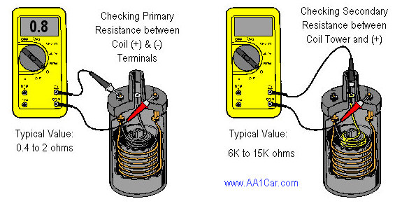
Testing resistance is a key step in checking the ignition control module. Resistance tells us if the internal coils and circuits work well. Using a multimeter, you can measure how much the module resists electrical flow. This helps find faults like breaks or shorts inside the module.
Resistance testing is simple and quick. It gives clear information about the module’s condition. Follow these steps carefully to get accurate readings and understand what they mean.
Measuring Coil Resistance
First, set your multimeter to the ohms (Ω) setting. This measures resistance. Locate the coil terminals on the ignition control module. Place the multimeter probes on these terminals. Hold them steady and note the reading on the display.
Make sure the module is disconnected from the power source. This prevents wrong readings or damage. Write down the resistance value shown. Repeat the test a few times for consistency.
Interpreting Resistance Values
Compare your readings to the manufacturer’s specifications. Normal coil resistance usually falls within a small range. A very high or infinite value means a broken coil wire. A very low value shows a short circuit inside the coil.
Resistance values outside the normal range indicate the module may fail soon. Replace the ignition control module if readings are off. Proper resistance ensures the module controls ignition timing correctly.
Checking Voltage Output
Checking the voltage output of the ignition control module is a key step. It shows if the module sends the correct signals to the ignition system. Using a multimeter helps measure these voltage signals accurately. This section explains how to connect the multimeter and read the voltage output properly.
Connecting Multimeter Leads
Set the multimeter to measure DC voltage. Connect the black lead to the module’s ground or chassis. Attach the red lead to the voltage output terminal of the ignition control module. Make sure the connections are secure and do not touch other wires. This setup ensures accurate voltage readings.
Reading Voltage Signals
Turn the ignition key to the “On” position without starting the engine. Watch the multimeter display for voltage readings. The voltage should rise and fall as the ignition module sends pulses. A steady or zero reading often means a faulty module. Note the voltage range and compare it with the vehicle’s specifications.
Testing Continuity
Testing continuity is a key step in checking an ignition control module. It helps to find breaks or faults in the electrical path. This test shows if electricity can flow through the module’s circuits. You will need a multimeter set to continuity mode. The process is simple but important for accurate diagnosis.
Multimeter Continuity Mode
Set your multimeter to continuity mode. This mode tests if two points are connected electrically. When connected, the multimeter beeps or shows a low resistance reading. If there is no beep or the reading is very high, the circuit is broken. Use the probes carefully to avoid short circuits.
Verifying Circuit Integrity
Touch the multimeter probes to the module’s terminals. Check each wire and connection inside the ignition control module. A beep means the circuit is complete and working. No beep means a broken wire or faulty component. Record the results to compare with the module’s specifications. This step ensures the module can pass current properly.

Credit: www.youtube.com
Analyzing Test Results
After testing the ignition control module with a multimeter, the next step is analyzing the test results. This step helps you understand if the module works properly or has faults. Careful analysis avoids wrong decisions and saves time and money.
Reading the multimeter display correctly is crucial. Each reading tells a story about the module’s condition. Knowing what to expect helps spot issues quickly.
Identifying Faulty Readings
Start by comparing your readings to the module’s specifications in the manual. Values outside the normal range often mean a problem. For example, a very high or very low resistance can show a broken connection inside the module.
Watch for sudden changes in readings during testing. Fluctuations may indicate internal damage. Also, check for zero or infinite readings, which usually point to a faulty module.
Deciding On Module Replacement
Once faulty readings appear, think about replacing the ignition control module. A bad module can cause engine misfires or no start issues. Repair is often not possible, so replacement is the best choice.
Use your test results to confirm the need for a new module. Replace the part promptly to avoid further engine damage. Always choose a quality replacement for long-lasting performance.
Tips For Accurate Testing
Testing an ignition control module with a multimeter requires care and precision. Small errors can lead to wrong results. Follow these tips for accurate testing. Correct steps make your work easier and safer.
Avoiding Common Mistakes
Check the multimeter settings before testing. Use the right mode, usually resistance or voltage. Connect the probes firmly to the module terminals. Loose connections cause false readings. Test the module at room temperature. Extreme heat or cold affects results. Do not touch metal parts of the probes. Your body can change the reading. Always turn off the vehicle before testing. This prevents damage to the multimeter and module.
Maintaining Multimeter Calibration
Calibration keeps your multimeter accurate. Test your multimeter on a known resistor or battery regularly. If readings are off, recalibrate or replace the device. Store the multimeter in a dry, safe place. Avoid dropping or exposing it to water. Clean the probes and contacts often. Dirt or rust causes poor connections. Proper care extends the multimeter’s life and ensures precise tests.
Credit: www.marineengine.com
Frequently Asked Questions
What Is An Ignition Control Module?
An ignition control module manages the ignition coil’s timing and firing in engines. It ensures efficient spark generation. Testing it helps diagnose engine misfires or starting issues. A faulty module can cause poor engine performance or stalling.
How Do You Test An Ignition Control Module?
To test, use a multimeter set to ohms. Measure resistance between module terminals as per the manual. Compare readings with manufacturer specifications. Abnormal values indicate a faulty ignition control module needing replacement.
Can A Multimeter Detect Ignition Control Module Failure?
Yes, a multimeter can detect resistance irregularities in the module. It helps identify internal shorts or open circuits. Proper testing ensures the module functions correctly and prevents engine problems.
What Are Signs Of A Bad Ignition Control Module?
Common signs include engine misfires, stalling, no start condition, and poor fuel economy. If these occur, testing the ignition control module with a multimeter is recommended to confirm failure.
Conclusion
Testing an ignition control module with a multimeter is simple. Follow the steps carefully to get accurate results. A working module helps your engine run smoothly. Faulty parts can cause starting problems or engine stalls. Regular checks keep your vehicle reliable and safe.
Use your multimeter to spot issues early. Save time and money on repairs by testing first. Keep this guide handy for quick reference. Your car will thank you for the care.