Are you struggling to figure out if your PCM (Powertrain Control Module) is working properly? Knowing how to test your PCM with a multimeter can save you time and money by pinpointing issues before they become costly repairs.
In this guide, you’ll discover simple, step-by-step instructions that anyone can follow—even if you’re not a tech expert. By the end, you’ll feel confident checking your PCM yourself and understanding the results. Ready to take control of your car’s health?
Let’s dive in.
Tools Needed
Testing a PCM (Powertrain Control Module) with a multimeter requires some basic tools. Having the right tools makes the process easier and more accurate. You need a good multimeter and a few extra items to complete the test safely.
Gathering all necessary tools before starting helps avoid mistakes. It also saves time and keeps you organized. The right tools ensure you get clear and reliable results from your PCM test.
Choosing The Right Multimeter
Pick a digital multimeter for better accuracy. Digital models show exact numbers on a screen. Look for a multimeter with voltage, resistance, and continuity settings. These functions are essential for testing a PCM.
A multimeter with a clear display and easy controls helps. It should measure low voltage signals since PCM circuits are sensitive. Avoid cheap or basic models that lack these features.
Additional Equipment
Use insulated test leads for safety and better contact. Sharp probe tips help reach small PCM pins and connectors. A wiring diagram of your vehicle’s PCM is useful. It shows pin layouts and signal types clearly.
Wear gloves to protect your hands from electric shocks. A flashlight might help you see wires and connectors better in dark engine bays. Keep a notebook to write down your readings and observations.
Pcm Basics
The Powertrain Control Module, or PCM, is a key part of your vehicle’s engine system. It controls many functions that keep the engine running smoothly. Understanding the basics of the PCM helps in diagnosing car problems. It also guides how to test the PCM with a multimeter. This knowledge can save time and money on repairs.
Role In Vehicle
The PCM acts like the brain of the engine. It receives data from sensors about engine speed, temperature, and air flow. Then, it adjusts fuel injection and ignition timing. This keeps the engine running efficiently. The PCM also manages emissions to reduce pollution. It controls the transmission shifting in many vehicles. Without a working PCM, the engine may stall or run poorly.
Common Issues
PCMs can fail due to heat, moisture, or electrical problems. Common symptoms include engine misfires, poor fuel economy, and trouble starting. The check engine light often turns on with PCM issues. Wiring problems or bad sensors can also cause false PCM errors. Testing the PCM with a multimeter helps find if the module is faulty or if other parts are causing problems.
Safety Measures
Testing a Powertrain Control Module (PCM) with a multimeter needs care. Safety must be the top priority to avoid damage or injury. Follow simple steps to protect yourself and the vehicle.
Disconnecting The Battery
Always disconnect the vehicle battery before testing the PCM. This stops electrical shocks and short circuits. Use a wrench to loosen the negative terminal first. Remove the cable and keep it away from the battery. Wait a few minutes to let the system fully power down. This step prevents accidental damage to the PCM and other parts.
Handling Precautions
Handle the PCM carefully to avoid static damage. Use an anti-static wrist strap if possible. Keep the module on a clean, dry surface. Avoid touching the pins or connectors directly. Never test the PCM with wet hands or in a damp area. These precautions help protect the sensitive electronics inside the PCM.
Preparing For Testing
Preparing to test the Powertrain Control Module (PCM) is crucial for accurate results. Before using a multimeter, you must take certain steps. These steps help ensure safety and effective testing. Understanding your vehicle and PCM layout is the first part of preparation.
Gather basic tools, including the multimeter, vehicle manual, and safety gloves. A clear workspace improves focus and prevents mistakes. Always disconnect the battery to avoid electrical shock or damage. Now, start with locating the PCM.
Locating The Pcm
The PCM is usually found in the engine bay or under the dashboard. Check your vehicle manual to find the exact location. It often appears as a small box with multiple wires attached. Clean the area around the PCM to access it easily. Knowing the PCM location saves time and effort during testing.
Accessing Connectors
PCM connectors hold the wiring to the module. You need to access these connectors for testing with a multimeter. Gently unplug the connectors without forcing them. Look for any signs of corrosion or damage on the pins. Clean connectors ensure accurate readings. Keep track of each connector’s position to avoid errors during reassembly.
Testing Voltage
Testing the voltage of a Powertrain Control Module (PCM) is a key step in checking its health. Voltage tests help identify if the PCM receives proper power. Without correct voltage, the PCM cannot work well. Measuring voltage is easy with a multimeter. This part explains how to set the multimeter and check the power supply.
Setting Multimeter To Voltage
First, turn on your multimeter. Select the voltage measurement mode. Use DC voltage (V with straight line) for PCM testing. Set the range to 20 volts for safety. Connect the black probe to the multimeter’s COM port. The red probe goes to the VΩmA port. This setup prepares your meter for voltage checking.
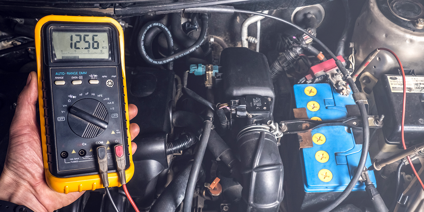
Checking Power Supply
Find the PCM power connector in your vehicle. Locate the power wire inside the connector. Place the black probe on a good ground point. Touch the red probe to the power wire pin. Watch the multimeter display for voltage reading. It should show around 12 volts. Lower or no voltage means a power supply issue. This step confirms the PCM gets enough power to work.
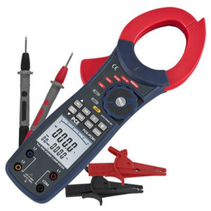
Credit: www.testequity.com
Testing Resistance
Testing resistance in a PCM (Powertrain Control Module) is an important step. It helps find electrical problems and ensures the PCM works well. Resistance tests check if circuits have the right amount of resistance. Too much or too little resistance can cause errors in the system.
This test uses a multimeter set to measure resistance (ohms). You need to know the correct resistance values for the PCM parts. These values come from the vehicle’s service manual. Follow safety steps and disconnect the battery before testing.
Measuring Ground Circuits
Ground circuits connect the PCM to the car’s chassis. They provide a path for electrical current. To test ground circuits, set the multimeter to the lowest resistance range. Connect one probe to the ground point on the PCM. Connect the other probe to the car’s frame or battery negative terminal.
A good ground circuit shows very low resistance, usually less than 1 ohm. High resistance means the ground circuit is faulty. Look for loose wires, corrosion, or broken connectors. Fix these issues to restore proper grounding for the PCM.
Inspecting Sensor Inputs
Sensor inputs send signals to the PCM. These signals help the PCM control the engine and other parts. To test sensor inputs, measure resistance across the sensor wires at the PCM connector. Compare the reading with the service manual’s specifications.
Resistance too high or too low means a problem with the sensor or wiring. Check the sensor’s condition and wiring harness. Replace damaged sensors or repair wires as needed. Accurate sensor inputs keep the PCM running smoothly and prevent engine issues.
Testing Continuity
Testing continuity is a key step in checking the PCM (Powertrain Control Module). It helps find if electrical paths are complete and working well. A multimeter set to continuity mode makes this task simple and quick. This test checks if wires and circuits inside the PCM have a proper connection or if there are breaks.
Verifying Wiring Connections
Start by turning off the power to the PCM. Set your multimeter to continuity mode. Touch the multimeter leads to both ends of the wire or connection point. A beep or a low resistance reading means good continuity. No sound or a high reading shows a possible break or loose wire. This step confirms wiring is connected correctly and ready to carry signals.
Detecting Breaks Or Shorts
Move the multimeter leads along the wire or circuit path. Listen for any breaks in the beep sound. No beep means a break in the wire or a bad connection. To find shorts, test between wires or to the ground. A beep here signals a short circuit. Detecting breaks or shorts early prevents bigger PCM problems later.
Interpreting Results
After testing the PCM with a multimeter, the next step is to understand the readings. Correct interpretation helps you find if the PCM works well or has issues. It shows if the electronic control unit controls the engine parts properly.
Readings vary based on the PCM model and vehicle type. Knowing what numbers mean normal or faulty saves time and money on repairs. Let’s explore how to tell good from bad results.
Normal Readings
Normal readings show stable voltage and resistance values. The multimeter should display values close to those in the vehicle’s service manual. For example, voltage often reads around 5 volts for control signals.
Resistance should not be zero or infinite. It usually falls within a specific range. Consistent values across tests mean the PCM circuits are fine. No sudden drops or spikes indicate healthy wiring and chips.
Signs Of Faulty Pcm
Faulty PCM readings include erratic voltages or no signal at all. Voltage below or above normal limits shows electrical problems inside the PCM. Infinite or zero resistance often means broken circuits or short circuits.
Unstable or changing values during the test point to internal damage. If readings differ greatly from the manual’s specs, the PCM likely needs repair or replacement. Faulty PCMs can cause engine troubles and warning lights.
Common Mistakes
Testing a PCM (Powertrain Control Module) with a multimeter can be tricky. Many beginners make simple errors that lead to wrong results. Avoiding these mistakes saves time and protects your vehicle’s electronics.
Understanding common mistakes helps you test the PCM correctly and safely. Focus on the details to get accurate readings.
Incorrect Multimeter Settings
Using the wrong setting on your multimeter is a frequent error. Set the multimeter to the correct mode before testing. For voltage checks, choose DC voltage. For resistance, select ohms.
Wrong settings can damage the multimeter or the PCM. Double-check your dial before connecting the probes. This step ensures you get valid test results.
Misreading Data
Reading the multimeter display incorrectly leads to confusion. Numbers on the screen show voltage, resistance, or continuity. Know what values to expect from the PCM.
Write down your readings and compare them with the PCM specs. Ignoring units or decimal points causes errors. Take your time to understand the data shown.
Credit: www.techshopmag.com
Next Steps After Testing
After testing the PCM with a multimeter, the next steps are crucial. These steps help you decide what to do based on your test results. Proper action ensures your vehicle runs smoothly and safely. Understanding repair options and knowing when to replace the PCM saves time and money.
Repair Options
If the PCM shows minor faults, repair might work. Some issues include loose connections or damaged wiring. Fixing these can restore PCM function. Cleaning corroded terminals also helps. Sometimes, reprogramming the PCM resolves errors. Use professional tools for reprogramming. Small repairs are cost-effective and quick.
When To Replace Pcm
Severe damage means replacement is necessary. Signs include burnt components or complete failure. A PCM that cannot hold a charge needs replacing. Replacement is also best if repairs fail repeatedly. Use original or high-quality aftermarket PCMs. Installation should be done by a skilled technician. Replacing the PCM ensures long-term vehicle reliability.

Credit: www.youtube.com
Frequently Asked Questions
How Do I Test Pcm With A Multimeter?
To test a PCM, set the multimeter to measure resistance or voltage. Check the wiring harness and connectors. Measure sensor outputs and compare with specifications. This ensures the PCM and sensors function correctly.
What Multimeter Settings Are Best For Pcm Testing?
Use the multimeter’s Ohm (Ω) setting to check resistance. Use the Volt (V) setting to measure voltage signals. These settings help diagnose PCM and sensor issues accurately.
Can A Multimeter Detect Pcm Faults?
Yes, a multimeter can detect faults like broken wires, bad sensors, or power issues. It helps diagnose electrical problems related to the PCM but may not identify internal PCM failures.
How Do I Check Pcm Sensor Signals?
Connect the multimeter probes to the sensor terminals. Measure voltage or resistance based on sensor type. Compare readings to manufacturer specs to verify sensor health.
Conclusion
Testing the PCM with a multimeter helps find car problems fast. Follow the steps carefully to get clear results. Keep your multimeter ready and check connections well. This simple test saves time and money on repairs. Practice a few times to feel confident and safe.
Now, you can handle basic PCM tests at home. Stay patient and check everything twice for best results.