When you work with electronics, sometimes you need to see what is happening inside a circuit. Two tools can help: logic analyzers and oscilloscopes. People often ask which one to use, or if you need both. The answer depends on what you are trying to measure, your project, and your skill level. This article will help you understand the differences, strengths, and weaknesses of each tool. You’ll also learn practical examples, real data, and tips that most beginners miss.
What Is A Logic Analyzer?
A logic analyzer is a device that captures and displays digital signals. These signals are usually 0s and 1s (low and high voltage). Logic analyzers are powerful for debugging digital circuits, like microcontrollers, communication buses (I2C, SPI, UART), and parallel data streams.
Unlike an oscilloscope, which shows the shape of a signal, a logic analyzer shows the state (high/low) of many channels at once. You can connect 8, 16, or even 32 wires. The analyzer records their changes over time. This helps you understand how data flows between chips.
Key Features Of Logic Analyzers
- Channels: Usually 8–32 digital inputs, sometimes more.
- Sampling Rate: Often between 10 MHz and 500 MHz. Higher rates mean more detail.
- Memory Depth: How much data it can store. Common values: 1–512 MB.
- Protocol Decoding: Converts raw signals into readable formats (e.g., shows “0xA5” for data bytes).
Example: Debugging I2c Communication
Suppose you have a sensor connected to a microcontroller using I2C. You want to see if the data is correct. With a logic analyzer, you can:
- Record the SDA and SCL lines.
- Decode the bytes sent and received.
- Check timing errors and missed bytes.
- Find problems that are invisible to the naked eye.
What Is An Oscilloscope?
An oscilloscope is a tool that shows the shape (waveform) of electrical signals. It’s used to measure both analog and digital signals. You can see voltage changes over time, measure frequency, amplitude, and noise.
Oscilloscopes are helpful for troubleshooting analog circuits (audio, power supplies, sensors) and checking fast pulses in digital systems.
Key Features Of Oscilloscopes
- Channels: Usually 2–4 analog inputs.
- Bandwidth: Typical values from 20 MHz to 1 GHz. Higher bandwidths capture faster signals.
- Sample Rate: Often 100 MSa/s to 5 GSa/s (million or billion samples per second).
- Display: Shows signal shape, voltage, and timing.
- Triggering: Helps capture specific events, like a button press.
Example: Measuring Noise In A Power Supply
Imagine you build a power supply. You want to check if there is unwanted noise. An oscilloscope lets you:
- Connect a probe to the output.
- See spikes, dips, or oscillations.
- Measure ripple voltage.
- Adjust your design to reduce noise.
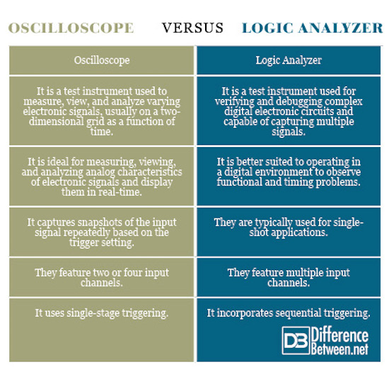
Credit: www.differencebetween.net
Core Differences: Logic Analyzer Vs Oscilloscope
Both tools show signals, but they do it in different ways. Here are the most important differences:
| Feature | Logic Analyzer | Oscilloscope |
|---|---|---|
| Type of Signal | Digital (high/low) | Analog & Digital (voltage waveform) |
| Channels | 8–32+ | 2–4 |
| Sampling Rate | 10–500 MHz | 100 MSa/s–5 GSa/s |
| Display | State diagram, protocol decoding | Waveform display |
| Use Case | Debugging digital buses | Measuring analog signals |
| Triggering | Complex (protocol-based) | Simple (voltage level, edge) |
When To Use A Logic Analyzer
Logic analyzers are best when you need to:
- Debug digital communication: Find errors in I2C, SPI, UART, CAN, or other buses.
- Capture many channels at once: Watch data flow across multiple wires.
- Decode protocols: See readable data, not just pulses.
- Analyze timing between digital events: Measure delays or check if signals overlap.
Hidden Benefits
Most beginners don’t realize that logic analyzers can:
- Record long sessions: You can capture hours of data, not just seconds.
- Find rare errors: If your circuit fails once every hour, a logic analyzer can help you catch it.
- Export data for analysis: You can use tools like Excel to study your results.
Common Mistakes
- Using a logic analyzer for analog signals (it won’t work).
- Setting a slow sampling rate—this can miss fast events.
- Ignoring protocol settings—wrong settings give confusing results.
When To Use An Oscilloscope
Oscilloscopes shine when you need to:
- See analog signals: Audio, sensor outputs, voltage changes.
- Measure frequency and amplitude: How fast and how strong is the signal?
- Check signal quality: Look for noise, distortion, or glitches.
- See signal shape: Square, sine, triangle, or custom waveforms.
Hidden Benefits
- Measure rise/fall time: How quickly a signal changes.
- Visualize glitches: Small errors are easy to spot.
- Test circuit response: See how a circuit reacts to changes.
Common Mistakes
- Using too low bandwidth—can miss fast changes.
- Incorrect probe setup—leads to wrong readings.
- Not using triggering—makes it hard to catch specific events.
Practical Comparison: Real World Examples
Let’s look at two real cases:
Case 1: Debugging Serial Data
You have a microcontroller sending data to a computer over UART. If the data is wrong, is the problem in the hardware or software?
- Logic Analyzer: Shows the bits sent, and decodes them into readable text. You can check if the microcontroller sends the right bytes.
- Oscilloscope: Shows the voltage waveform. You can see if the signal is noisy, too weak, or distorted.
Case 2: Measuring Sensor Output
You want to check a temperature sensor connected to your circuit.
- Logic Analyzer: Only useful if the sensor uses a digital protocol (like I2C).
- Oscilloscope: Useful for analog sensors. You can see the output voltage and measure changes as temperature changes.
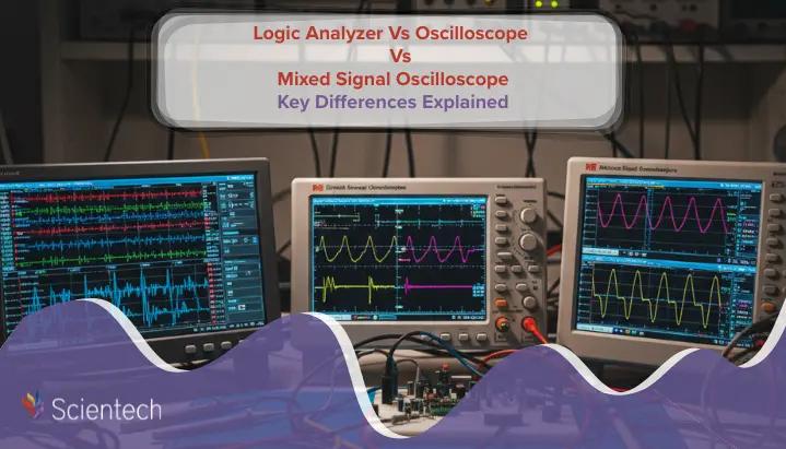
Credit: scientechworld.com
Price And Availability
Both tools come in many prices and sizes. Here’s a quick comparison:
| Price Range | Logic Analyzer | Oscilloscope |
|---|---|---|
| Entry Level | $30–$200 | $100–$400 |
| Professional | $500–$5000+ | $1000–$10,000+ |
| Portability | Often USB, small | Benchtop or handheld |
| Software | PC-based, protocol decoding | Built-in screen, PC connection optional |
Some small logic analyzers (like Saleae, Open Logic Sniffer) are affordable and easy to carry. Oscilloscopes are usually bigger, but now you can find USB scopes for laptops.
Choosing The Right Tool For Your Project
When deciding, think about:
- Signal Type: If you need to measure voltage shapes, use an oscilloscope. For digital states, use a logic analyzer.
- Number of Channels: If your circuit has many lines, logic analyzers are better.
- Protocol Decoding: If you need to understand digital communication, logic analyzers save time.
- Budget: Entry-level logic analyzers are cheaper, but basic oscilloscopes are more versatile.
- Skill Level: Oscilloscopes need more practice to use well.
Comparison Table: Quick Decision Guide
| Project Type | Recommended Tool |
|---|---|
| Microcontroller Debugging | Logic Analyzer |
| Audio Signal Analysis | Oscilloscope |
| Sensor Output (Analog) | Oscilloscope |
| Bus Protocol Decoding | Logic Analyzer |
| Power Supply Testing | Oscilloscope |
Advanced Insights: What Most Beginners Miss
Many new users think one tool can do everything. But even advanced oscilloscopes with “logic analyzer” functions have limits. Here are two important points:
- Bandwidth vs. Sample Rate: Oscilloscopes can capture fast signals, but their memory depth is usually smaller. Logic analyzers can record longer sessions, but miss analog details.
- Protocol Decoding Quality: Entry-level oscilloscopes may offer basic protocol decoding, but a real logic analyzer gives richer, easier-to-read results.
If you work on complex digital projects, consider both tools. Advanced engineers often use them together. For example, you might use an oscilloscope to check signal quality, then a logic analyzer to debug data flow.
Software And Data Export
Modern tools let you save data and analyze it later. Logic analyzers often have better export features for digital analysis. Oscilloscopes can export waveforms for offline study.
Some software lets you connect both devices to your PC, so you can see analog and digital data side by side. For more details on combined analysis, visit Wikipedia.

Credit: www.batterfly.com
Frequently Asked Questions
What Is The Main Difference Between A Logic Analyzer And An Oscilloscope?
A logic analyzer captures digital (high/low) signals across many channels and decodes them into readable formats. An oscilloscope shows the shape of analog or digital signals, focusing on voltage changes over time.
Can An Oscilloscope Be Used As A Logic Analyzer?
Some advanced oscilloscopes offer basic logic analysis, but usually with fewer channels and less protocol decoding. For deep digital debugging, a dedicated logic analyzer works better.
Which Tool Is Better For Microcontroller Projects?
If you need to debug communication (like I2C, SPI, UART), a logic analyzer is best. If you want to check voltage levels or signal quality, use an oscilloscope.
Are There Devices That Combine Both Functions?
Yes, some high-end oscilloscopes include digital channels and protocol decoding. However, they are expensive and may not offer the same channel count or features as standalone logic analyzers.
How Do I Choose The Right Sampling Rate?
For logic analyzers, the sampling rate should be at least 5–10 times faster than the signal you want to capture. For oscilloscopes, higher sample rates and bandwidths help you see fast and accurate waveforms.
Choosing between a logic analyzer and an oscilloscope is not always easy. Both tools are essential in electronics, each with strengths and weaknesses. The best engineers learn to use both, depending on their project needs. Start by understanding your signals and goals—then pick the tool that helps you see clearly.
With the right instrument, you can solve problems faster and build better circuits.