Signal Generator Vs Oscilloscope: Complete Guide
If you’ve ever worked with electronics, you know the importance of measuring and testing signals. Two essential tools for this job are the signal generator and the oscilloscope. These devices look similar, but they serve very different purposes. Many beginners confuse them or don’t know which one to use. Understanding their differences helps you troubleshoot, design, and test circuits more efficiently.
This article explains what each tool does, how they work, and when to use them. You’ll see practical examples, learn about their main features, and get clear advice on choosing the right tool for your needs. Whether you are a student, hobbyist, or engineer, you’ll find useful tips and non-obvious insights to help you make confident decisions.
What Is A Signal Generator?
A signal generator is a device that creates electronic signals. These signals can be different shapes, like sine waves, square waves, or pulses. The main job of a signal generator is to produce signals that you can use to test other devices or circuits.
For example, if you build an audio amplifier, you can use a signal generator to send a test tone into the amplifier. Then, you check if the amplifier works as expected.
Types Of Signal Generators
There are several kinds of signal generators, each designed for specific tasks:
- Function Generators – Produce basic waveforms like sine, square, triangle, and sawtooth.
- RF Signal Generators – Create radio frequency signals for testing wireless communication devices.
- Pulse Generators – Make pulses for digital circuits or timing analysis.
- Arbitrary Waveform Generators – Allow custom waveforms, useful for complex testing.
Key Features And Specifications
When choosing a signal generator, you should consider:
- Frequency Range – How low and high the device can go. Audio function generators usually handle up to 20 kHz, while RF generators can reach several GHz.
- Amplitude Control – Adjusts the strength (voltage) of the signal.
- Waveform Options – Look for sine, square, triangle, and more.
- Output Impedance – Important for matching the generator to your circuit.
A basic function generator might cover 0. 1 Hz to 1 MHz, with amplitude up to 20 V peak-to-peak.
Example Use Cases
- Testing audio equipment with sine waves.
- Checking microcontroller timing with pulses.
- Simulating sensor signals in industrial equipment.
Many beginners miss the importance of output impedance. If it does not match the circuit, your test results may be wrong. Always check this before connecting.
What Is An Oscilloscope?
An oscilloscope is a device that displays electrical signals on a screen. It shows how the voltage changes over time, letting you see the signal’s shape, frequency, and amplitude. Unlike a signal generator, an oscilloscope does not create signals—it only observes them.
Think of an oscilloscope as a window into your circuit. You can see if the signal is clean, noisy, distorted, or missing.
Main Functions Of An Oscilloscope
- Waveform Visualization – See real-time signal shapes.
- Measurement Tools – Measure frequency, peak-to-peak voltage, period, rise time, and more.
- Triggering – Capture specific parts of a signal for detailed analysis.
- Storage and Analysis – Save waveforms and perform calculations.
Modern digital oscilloscopes offer advanced features like automatic measurements, USB storage, and math functions.
Important Specifications
- Bandwidth – The maximum frequency the oscilloscope can accurately display. Entry-level models may have 20 MHz bandwidth, while professional models go up to 1 GHz or more.
- Sample Rate – How often the oscilloscope records data points. Higher rates give more detail.
- Number of Channels – How many signals you can view at once (usually 2 or 4).
- Vertical Resolution – Measured in bits; higher means more precise voltage readings.
Here’s a comparison of typical oscilloscope specifications:
| Model | Bandwidth | Sample Rate | Channels |
|---|---|---|---|
| Basic Digital | 50 MHz | 500 MS/s | 2 |
| Mid-range | 200 MHz | 2 GS/s | 4 |
| High-end | 1 GHz | 5 GS/s | 4+ |
Example Use Cases
- Troubleshooting faulty circuits by viewing signal shapes.
- Measuring timing in digital systems.
- Checking audio signals for distortion.
- Observing RF signals in communication devices.
One insight many beginners miss: bandwidth is not just about frequency. A low-bandwidth oscilloscope can miss fast glitches or spikes, even if your main signal is slow.
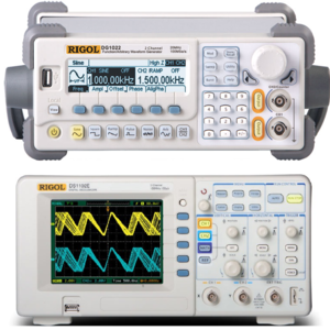
Credit: june.uoregon.edu
Signal Generator Vs Oscilloscope: Core Differences
It’s easy to confuse these two devices, but their roles are fundamentally different. Here’s a summary:
| Feature | Signal Generator | Oscilloscope |
|---|---|---|
| Function | Creates signals | Measures signals |
| Output | Provides voltage waveform | Displays waveform |
| Input | None (output device) | Receives from circuit |
| Waveform Types | Sine, square, triangle, custom | Any signal present |
| Main Use | Testing, simulation | Troubleshooting, analysis |
| Examples | Audio, RF, digital logic | Audio, RF, digital logic |
The signal generator is like a “producer”—it makes signals. The oscilloscope is the “observer”—it shows what’s happening in your circuit.
Practical Applications: When To Use Each Tool
Understanding when to use a signal generator or oscilloscope saves time and avoids mistakes.
Common Scenarios
- Designing a Circuit
- Use a signal generator to simulate inputs.
- Use an oscilloscope to check outputs and see if the circuit works.
- Troubleshooting
- Inject known signals from the generator.
- Observe with the oscilloscope to find where problems occur.
- Testing Frequency Response
- Sweep frequencies with the generator.
- Use the oscilloscope to see how the circuit responds.
- Verifying Timing
- Use pulse generators for digital circuits.
- Oscilloscope checks timing, delays, and glitches.
Real-world Example
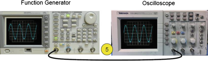
Imagine you are testing a filter circuit. You use a signal generator to send a range of frequencies into the filter. The oscilloscope shows how the signal changes after passing through the filter. By comparing input and output signals, you can see if the filter blocks or passes certain frequencies.
Many beginners overlook the value of combining both tools. For complex circuits, using both together gives a much clearer picture of performance.

Credit: www.youtube.com
Key Specifications Compared
Comparing the main specifications helps you understand which tool fits your needs.
| Specification | Signal Generator | Oscilloscope |
|---|---|---|
| Frequency Range | 0.1 Hz–1 GHz+ | Up to 1 GHz+ |
| Amplitude | Up to 20 V (typical) | Measurement only |
| Waveform Options | Sine, square, triangle, custom | Any present waveform |
| Channels | 1–2 (sometimes more) | 2–4 (sometimes more) |
| Special Features | Sweep, modulation, burst | Triggering, math, storage |
Choosing The Right Tool
Selecting between a signal generator and oscilloscope depends on your project goals.
- If you need to create test signals, you need a signal generator.
- If you need to observe or measure signals, you need an oscilloscope.
For most electronics labs, both are essential. Beginners sometimes think they can replace one with the other, but that leads to confusion and missed problems.
Tips For Buyers
- Don’t buy the cheapest oscilloscope or signal generator. Low-quality devices can miss important details.
- Check bandwidth and frequency range before buying.
- Consider future needs—choose a device that can handle your upcoming projects.
- Read reviews from professionals and check technical specs. For deeper information, visit Wikipedia.
A less-known insight: oscilloscopes often include built-in signal generators for basic tasks, but their performance is limited. Don’t rely on this feature for advanced testing.
Common Mistakes Beginners Make
1. Using A Signal Generator To Measure Signals
A signal generator cannot measure—it only outputs signals.
2. Using An Oscilloscope As A Source
Oscilloscopes do not output test signals; they only display them.
3. Ignoring Output Impedance
Not matching impedance can cause inaccurate results.
4. Selecting Wrong Frequency Range
Buying a device with too low a range limits future experiments.
5. Not Understanding Bandwidth Limits
Bandwidth affects what you can see or test. Low bandwidth misses fast signals.
6. Skipping Calibration
Devices need calibration for accurate results. Check this before use.
Advanced Tips: Getting More From Your Equipment
- Use the signal generator’s sweep function to test frequency response automatically.
- Take advantage of oscilloscope triggering to capture rare events or glitches.
- For digital circuits, synchronize the signal generator and oscilloscope to analyze timing.
- Use the oscilloscope’s math functions to compare two signals directly.
Many beginners don’t realize: for sensitive measurements, shield cables and keep them short to reduce noise.
Credit: link.springer.com
Frequently Asked Questions
What Is The Main Difference Between A Signal Generator And An Oscilloscope?
A signal generator creates electronic signals for testing, while an oscilloscope displays and analyzes signals from circuits. One is a source, the other is a measurement tool.
Can I Use A Signal Generator As An Oscilloscope?
No. A signal generator cannot measure or display signals. It only outputs waveforms for testing other devices.
What Are The Most Important Specs To Check For An Oscilloscope?
Check bandwidth, sample rate, number of channels, and vertical resolution. Higher bandwidth and sample rates mean you can see faster and more detailed signals.
Why Does Output Impedance Matter In Signal Generators?
Output impedance affects how the signal interacts with your circuit. If it doesn’t match, the signal may be distorted or reduced, leading to incorrect test results.
Do I Need Both Devices For A Home Electronics Lab?
Yes, if you plan to build, test, or troubleshoot circuits regularly. Each device serves a unique purpose and together they give a complete picture of how your electronics work.
Electronics can feel complex, but with the right tools and clear understanding, you can solve problems faster and build better projects. Signal generators and oscilloscopes are partners in making electronics reliable and easy to master.