Oscilloscope probes are essential tools for anyone working with electronics. When you use an oscilloscope, the probe is your bridge between the circuit and the instrument. But there’s a detail that can confuse many beginners: the choice between 1X and 10X probe settings. This small switch can change your measurements, your troubleshooting, and your results in big ways. If you’ve ever wondered what the difference is, which to use, or how these settings impact your work, this guide will help you understand with clear explanations, real-world examples, and practical advice.
What Are Oscilloscope Probe Attenuation Settings?
Every oscilloscope probe comes with a switch or setting, usually labeled 1X and 10X. These numbers refer to the attenuation factor. In simple terms, attenuation means how much the signal is reduced before it reaches the oscilloscope.
- 1X means the probe passes the signal directly, without reducing it.
- 10X means the probe reduces the signal by a factor of ten before it reaches the scope.
So, if you measure a 5V signal in 1X mode, the oscilloscope sees 5V. In 10X mode, the oscilloscope sees 0. 5V, but it multiplies the displayed reading by 10 to show the real voltage.
This setting is not just about numbers. It affects signal quality, measurement accuracy, and even the safety of your equipment.
How 1x And 10x Probes Work
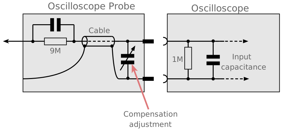
Oscilloscope probes are more than simple wires. They contain resistors and capacitors to help capture signals accurately. The probe’s attenuation setting changes the internal circuit.
1x Probe
- Direct connection: The probe connects your circuit to the oscilloscope with almost no resistance.
- Bandwidth: Typically limited, often below 10 MHz for most standard probes.
- Loading effect: Higher. The probe draws more current from the circuit, which can change the signal you’re measuring.
- Use case: Good for low-frequency signals, such as audio, simple digital, or power supply voltages.
10x Probe
- Attenuation: The probe adds a resistor (usually 9 MΩ) in series, so only one-tenth of the voltage reaches the oscilloscope.
- Bandwidth: Much higher, often up to 100 MHz or more.
- Loading effect: Much lower. The probe draws less current, preserving the original signal shape.
- Use case: Best for high-frequency signals, sensitive analog circuits, and when accuracy matters.

Credit: www.youtube.com
Key Differences Between 1x And 10x Probe Settings
Let’s look at the main differences in a clear way. Here’s a summary table showing how 1X and 10X compare across important factors:
| Feature | 1X Probe | 10X Probe |
|---|---|---|
| Attenuation | None | 10x reduction |
| Input Resistance | ~1 MΩ | ~10 MΩ |
| Bandwidth | Low (<10 MHz) | High (>100 MHz) |
| Signal Loading | High | Low |
| Accuracy | Good for low freq | Good for all freq |
| Use Cases | Audio, logic | RF, fast digital |
This comparison shows why the right setting is critical. Using 1X for high-frequency signals can distort your results. Using 10X for very small voltages can make them hard to see.
Why Probe Loading Matters
Probe loading is a term that’s often overlooked. It means how much the probe changes the circuit just by being connected. This is especially important in sensitive circuits.
- 1X probes have lower resistance, so they draw more current. This can cause the voltage in your circuit to drop, making your measurements wrong.
- 10X probes have higher resistance, so they draw less current. This helps keep your circuit running as it should.
For example, if you measure a 3. 3V signal with a 1X probe in a circuit with a high output resistance, you might see only 2. 8V or even less. With a 10X probe, you’d see the true voltage. This is a mistake many beginners make, especially when working with analog sensors or microcontroller outputs.
Bandwidth: How Fast Is Your Probe?
Bandwidth means how quickly your probe can respond to changes in the signal. If your probe’s bandwidth is too low, fast signals will look slower, with rounded edges.
- 1X probes are limited by the oscilloscope’s input circuit. They often can’t handle signals faster than 10 MHz.
- 10X probes are designed for speed, often rated for 100 MHz or more.
If you’re looking at digital signals, clocks, or radio frequencies, using a 1X probe will hide details. You’ll see slow, inaccurate shapes instead of crisp transitions.
Signal Amplitude And Noise
Another difference is how much voltage the oscilloscope can safely handle. In 1X mode, the scope sees the full signal. If you connect a 20V line, you risk damaging the oscilloscope.
- 10X mode lets you measure higher voltages safely, up to 100V or more, depending on the probe.
- 1X mode is often limited to 10V or less.
Noise is also important. 10X probes can sometimes introduce more noise because of the higher resistance. But for most signals, the benefit of lower loading outweighs this.
When To Use Each Setting
Choosing the right probe setting is not always obvious. Here are practical cases:
- Low-frequency, low-voltage signals: Use 1X. You’ll see the signal clearly, and the loading effect is less important.
- High-frequency or sensitive signals: Use 10X. You get more accurate shapes and less distortion.
- Measuring high voltages: Always use 10X. Protect the oscilloscope and yourself.
- Debugging digital circuits: For slow logic (under 10 MHz), 1X is fine. For fast clocks or data lines, switch to 10X.
It’s easy to forget to check your probe setting. Always look at the switch before starting measurements.
Practical Example: Measuring A Microcontroller Signal
Imagine you’re testing a microcontroller output pin. The pin switches between 0V and 3.3V at 1 MHz.
- With a 1X probe, you might see rounded edges and a lower peak voltage, maybe 2.7V.
- With a 10X probe, you see sharp transitions, and the voltage reads accurately.
If you’re troubleshooting why your circuit isn’t working, this difference can lead you to the wrong answer.
Common Mistakes Beginners Make
- Leaving the probe on 1X all the time: Many think 1X is “better” because it’s direct. But this can cause errors, especially with fast or high-voltage signals.
- Forgetting to set the oscilloscope: When you change the probe to 10X, you must tell the oscilloscope. If you don’t, the readings will be off by a factor of ten.
- Using 1X for high-frequency signals: This limits bandwidth and distorts waveforms.
- Not checking probe compensation: Probes must be calibrated to the oscilloscope. Skipping this step leads to inaccurate shapes.
How To Set Up Probes Correctly
Always follow these steps when connecting probes:
- Check the probe setting: Is it 1X or 10X?
- Set the oscilloscope input: Most scopes let you choose probe attenuation.
- Compensate the probe: Use the oscilloscope’s test output to adjust the probe until square waves look square.
- Verify the voltage range: Make sure the probe and oscilloscope can handle your signal.
- Start with 10X for unknown signals: It’s safer, especially with higher voltages.
Credit: www.electronics-notes.com
Real Data: How Probe Settings Affect Measurements
Here’s a simple test. Measure a 5V, 1 MHz square wave with both probe settings.
| Probe Setting | Observed Peak Voltage | Rise Time | Shape Accuracy |
|---|---|---|---|
| 1X | 4.6V | 120ns | Rounded edges |
| 10X | 5.0V | 60ns | Sharp edges |
This shows the importance of probe selection. Using 10X gives you the true voltage and shape. Using 1X can hide problems, especially in digital circuits.
Safety Considerations
Oscilloscopes are sensitive instruments. Using the wrong probe setting can damage the equipment or give dangerous readings.
- Always use 10X for high voltages. If you’re unsure, start with 10X.
- Double-check oscilloscope limits. Most scopes have a maximum voltage input. 10X probes extend this limit.
- Don’t touch exposed probe tips when measuring high voltage.
These steps protect you and your equipment.
Advanced Insights: Probe Compensation And Parasitics
Many beginners miss the importance of probe compensation. Each probe must be adjusted to match the oscilloscope’s input. This is done using a small screw on the probe and the oscilloscope’s calibration signal.
Improper compensation leads to distorted square waves and inaccurate measurements. Always check compensation every time you connect a probe.
Another advanced point is parasitic capacitance. All probes add a little capacitance to the circuit. In high-speed circuits, even a small extra capacitance can change timing and cause errors. Using 10X reduces this effect, making your measurements more reliable.
Oscilloscope Probe Selection Checklist
If you’re choosing a probe for your oscilloscope, consider these factors:
- Bandwidth: Match the probe’s bandwidth to your signal.
- Voltage range: Make sure the probe can handle your signal voltage.
- Probe attenuation: Choose 10X for most signals, 1X for low-frequency, low-voltage.
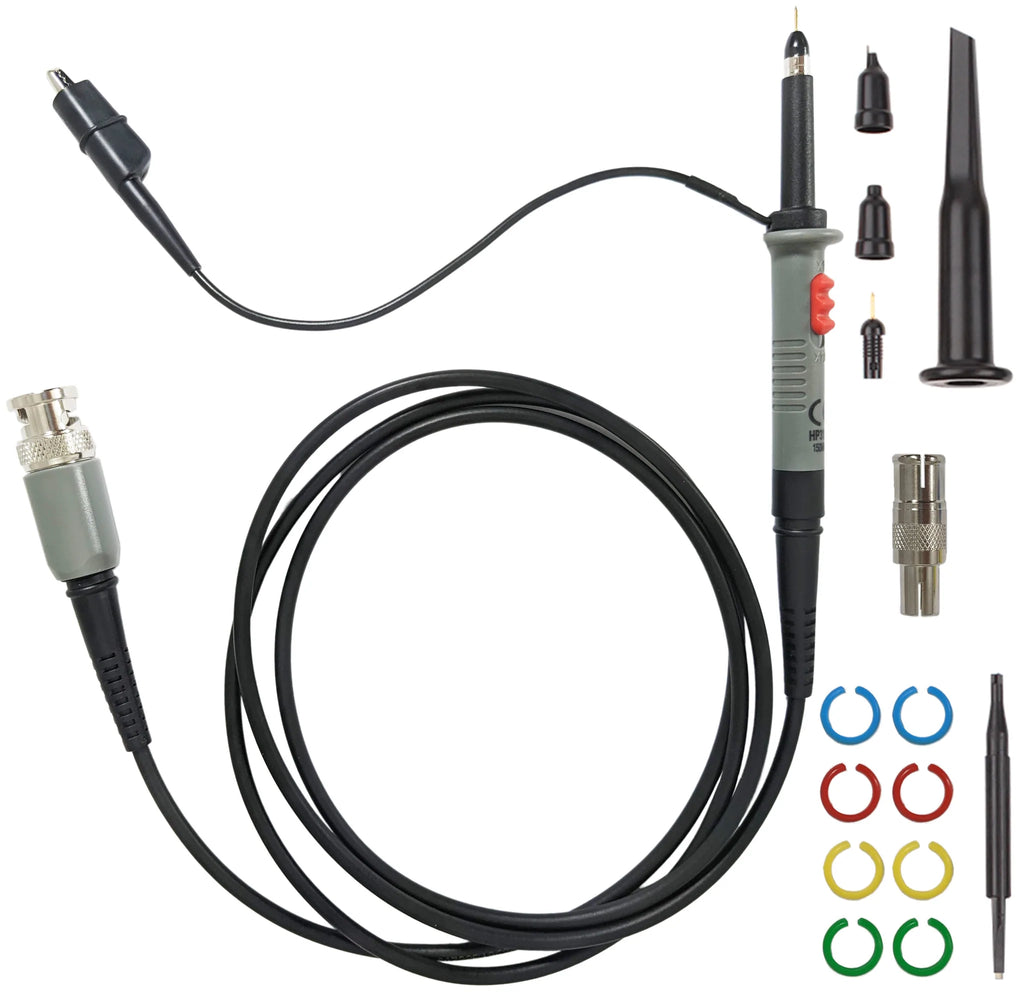
- Connector type: BNC is most common.
- Cable length: Shorter cables reduce noise and distortion.
Don’t just pick the probe that comes with your oscilloscope. Sometimes, upgrading to a better probe improves your results.
Credit: www.elexp.com
Common Questions About 1x Vs 10x
Understanding the differences can be tricky. Here’s a summary table to help you decide:
| Scenario | Recommended Setting |
|---|---|
| Audio signals (low freq) | 1X |
| High-speed digital | 10X |
| High-voltage circuits | 10X |
| Sensor outputs | 10X |
| Power supplies | 10X |
Frequently Asked Questions
What Happens If I Use A 1x Probe For High-frequency Signals?
A 1X probe has limited bandwidth and high loading. This means fast signals will look slower, and the shape will be distorted. You might miss glitches or errors in digital circuits.
Why Does My Oscilloscope Show The Wrong Voltage When I Switch Probe Settings?
If you change from 1X to 10X but do not update the oscilloscope’s probe setting, your readings will be ten times too low. Always set the probe attenuation in the oscilloscope menu.
Is It Safe To Measure High Voltages With A 1x Probe?
No. Most 1X probes are rated for low voltages (usually below 10V). Measuring higher voltages can damage your oscilloscope or create a safety risk. Use a 10X probe for high voltages.
Do I Need To Compensate My Probe Every Time?
Yes, especially when switching probes or oscilloscopes. Probe compensation ensures square waves look correct and measurements are accurate.
Where Can I Learn More About Oscilloscope Probes?
You can read more about oscilloscope probes and their settings at Wikipedia, which covers technical details and practical advice.
Choosing between 1X and 10X probe settings may seem simple, but it can change how you see and understand your circuits. By knowing the differences, avoiding common mistakes, and setting up your equipment correctly, you’ll get the best results every time.
Whether you’re a beginner or an experienced engineer, careful probe selection is key to reliable measurements and safe testing.